NPTF stands for “National Pipe Taper Fuel”. It is a tapered pipe thread per ASTM B 1.20.3, derived from the more common NPT standard. It is often referred to as “Dryseal thread”. The tolerances of NPTF are tighter and create a “Metal to Metal” contact between the male and female parts, thus creating a better seal without the need for sealing material. It is commonly used in hydraulic, fuel, and other applications requiring a tight, leak-proof connection.
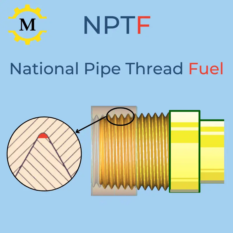
Table of Contents
NPTF Vs. NPT
Tolerancing and Acceptance
Most of the dimensions of NPTF threads are identical to NPT. The main difference are the tolerance requirements which are more strict for NPTF.
Mating and Truncation Tolerances
When internal and external pipe threads are tightened, one of three mating conditions can occur: Clear, Contact, or interference.

| NPTF | NPT |
|---|---|
| Separate truncation tolerance for root and crest | The root and the crest share the sane tolerance |
| Tight truncation tolerance field of about 2%-4% of the pitch. | Truncation tolerance is about 3%-6% of the pitch |
| * LMC creates contact between the root and the crest. * MMC creates interference between the root and the crest.. | Mating crests and roots may clear, contact, or interfere. The thread may not necessarily seal unless a sealant is used. |
Taper Angle Tolerance
The nominal taper angle is 1.709° for both standards. However, the tolerance field in NPTF is 0.3°, and NPT 0.5°. The outcome of both the taper and the truncation having tighter control leads to higher repeatability of sealing performance when using NPTF threads.
Gauging for acceptance
- The NPT standard requires only an L1 Gage.
- NPTF requires, in addition to the L1 gage, also: L2, L3, and “Crest Check” gages.
Production Cost
- Machining: The production process for NTF and NPT is the same. Therefore the machining cost is identical.
- Inspection: The NPTF standard requires 3 gaging tests for acceptance (Only one in NPT). Therefore the inspection cost of NPTF is higher.
- Quality: The scrap rate in the production of NPTF threads is higher. An unattentive worker can easily produce nonconforming parts. This is the most significant factor that increases the cost of NPTF threads.
Sealing Performance
- NPTF root and crest truncation tolerances are adjusted for an interference fit which creates a mechanical seal through thread form deformation at assembly. There is no need for PTFE, Teflon tapes, or any other sealant.
- NPT needs a sealant to be leak-free. A sealing material such as PTFE or Teflon must be used to prevent leaks.
When is it necessary to use a mechanical seal?
- Using sealants could contaminate the fluids or gasses flowing through the system.
- A sealant might fail because of high heat or high pressure.
List of Series defined in ASME B1-20.3
| Name | Description | |
|---|---|---|
| National Pipe Taper Fuel | The primary series for all service conditions. | |
| Short Pipe Tapar Fuel | Saves raw material where a full thread engagement length is not critical | |
| National Pipe Straight Fuel | Internal only straight thread for ductile materials | |
| National Pipe Straight Intermediate | Internal only straight thread for hard materials |
Designations of Dryseal Pipe Threads
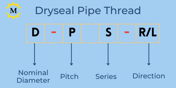
Basic designation syntax:
- Nominal Diameter in Inch Fraction
- Pitch in TPI
- Series: NPTF / PTF-SAE / NPSF / NPSI.
- Direction
Diameter:
- The diameters are given in inch fractions. For example, 1/4″, 3/4″, and 1 1/4″.
- It is also allowed to denote the diameters with a decimal value. For example, 0.250 (1/4″), 0.4375 (7/16″), etc.
Pitch:
- By default, the pitch is given in TPI. For example, 1/4-20 means a thread with a pitch of 20 TPI (1/20=0.05″).
- It is also allowed to denote the pitch by distance. For example, 1/4-0.05P means a thread with a pitch of 0.05″ (same as 20 TPI).
Series:
NPTF, PTF, NPSF, or NPSI. Where the meaning of each letter is:
- N = National
- P = Pipe
- T = Taper
- S = Straight
- F = Fuel
- I = Intermediate
Additional Parameters:
- Direction: By default, the thread is right-hand. For a left-hand thread, add the suffix -LH.
NPTF series – National Pipe Taper Fuel Thread
NPTF stands for National Pipe Tapered Fuel. . The basic profile is identical to the common NPT thread. The main difference is that NPTF provides a leakproof seal without using a sealant. It is obtained by tight tolerances and gauging requirements that create interference fitting in all conditions. The thread profile is tapered at an angle of 1°47′ (0.0625 Inch per inch of length) relative to the axis. Learn more about the difference between NPTF & NPT.
The profile properties, such as height, pitch, and truncations, are constant. However, the pitch diameter is not a constant value. It changes depending on the distance from the beginning of the thread.
Because of that, the set of parameters and measuring techniques is very different (and often confusing) compared to Unified Inch and metric threads.
To make the explanations and drawings more straightforward, we split them into 3 sections:
- An assembly drawing of an External and Internal thread showing only the parameters that are either common to both or are relevant to the assembly.
- External thread drawing with all its relevant dimensions.
- Internal thread drawing with all its relevant dimensions.
Common Dimensions (External & Internal)
When assembling with “hand force”, the male and female parts of a tapered thread will turn several rotations until the clearance is closed, and a “stop” is reached. This distance is called “Hand Tight Engagement Length”, and an “L1 Gauge usually measures it”. To form the seal, the assembly continues with a wrench an additional distance called “Wrench Allowance”.
NPTF Pipe & Fitting Assembly Drawing

Symbols
| Symbol | Name | Explnation |
|---|---|---|
| P | pitch | Given in TPI, and used in calculations as distance |
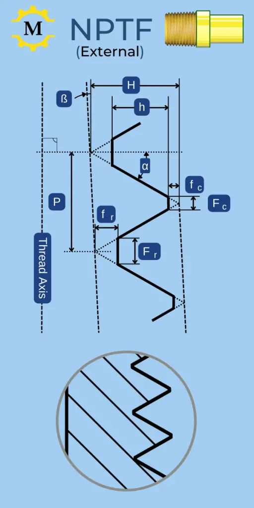
| ß | Thread Tapper Angle |
|
| α | Thread V half Angle |
|
| H | Height of the "sharp V" |
The height of the theoretical profile triangle.
\( H=\frac{\sqrt{3}}{2}\times{P} \) |
| h | Thread Height |
Distance between the truncated root and crest. It is a result of the truncation tolerances as defined in the Below Chart. |
| L1 | Length of hand-tight engagement | The maximum distance that the male and female parts can be threaded by normal hand force. |
| E1 | Pitch diameter at the L1 Plane | The Pitch d diameter at the plane of hand-tight engagement length (L1) of external thread (Pipe), and at the large end of internal thread (Fitting) |
| L1 - L2 | Maximum Wrenching Distance | To create a seal, the pipe and fitting should be further tightened by a wrench beyond the L1 plane. |
| L3 | Minimum Wrenching Distance |
NPTF External Thread Dimensions
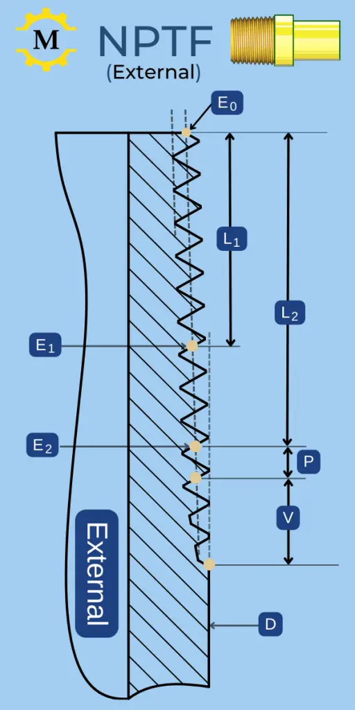
Basic Drawing
Profile Drawing
Symbols
| Symbol | Name | Explnation | ||
|---|---|---|---|---|
|
P, H, h, L1, E1 α, and ß are defined in the assembly section above. |
||||
| D | Pipe OD | Outer diameter of the pipe | ||
| E0 |
Pitch Diameter at the Pipe's end |
E0=D - (O.O5*D + 1.1 ) * P |
||
| L2 | Length of Last usefull Thread | Length of Last proper Thread. At L2, the thread profile starts to get truncated, but it is still considered "useful" until this point. | ||
| E2 | Pitch Diameter at E2 plane |
E2 = E0 + 0.0625 * L2 |
||
| V | Length of Vanish threads |
The length of "Unuseful" threads. |
||
Basic Dimensions Chart – NPTF External Threads
- Dimensions are in Inches. To view metric values, click the Thread Description link.
- There are a total of 20 parameters for each thread size. The below charts show only the main ones. To view all the parameters, click the thread description link.
| wdt_ID | wdt_created_by | wdt_created_at | wdt_last_edited_by | wdt_last_edited_at | Thread | Pipe | pipe OD | TPI | Pitch | End Pitch Diameter (E0) | Engagement Length (L1) |
|---|---|---|---|---|---|---|---|---|---|---|---|
| 1 | erezsp1966@gmail.com | 17/11/2024 12:55 PM | erezsp1966@gmail.com | 17/11/2024 12:55 PM | 1/16 - 27 NPTF | 1/16" | 0.31 | 27 | 0.0370 | 0.2712 | 0.1600 |
| 2 | erezsp1966@gmail.com | 17/11/2024 12:55 PM | erezsp1966@gmail.com | 17/11/2024 12:55 PM | 1/8 - 27 NPTF | 1/8" | 0.41 | 27 | 0.0370 | 0.3635 | 0.1615 |
| 3 | erezsp1966@gmail.com | 17/11/2024 12:55 PM | erezsp1966@gmail.com | 17/11/2024 12:55 PM | 1/4 - 18 NPTF | 1/4" | 0.54 | 18 | 0.0556 | 0.4774 | 0.2278 |
| 4 | erezsp1966@gmail.com | 17/11/2024 12:55 PM | erezsp1966@gmail.com | 17/11/2024 12:55 PM | 3/8 - 18 NPTF | 3/8" | 0.68 | 18 | 0.0556 | 0.6120 | 0.2400 |
| 5 | erezsp1966@gmail.com | 17/11/2024 12:55 PM | erezsp1966@gmail.com | 17/11/2024 12:55 PM | 1/2 - 14 NPTF | 1/2" | 0.84 | 14 | 0.0714 | 0.7584 | 0.3200 |
| 6 | erezsp1966@gmail.com | 17/11/2024 12:55 PM | erezsp1966@gmail.com | 17/11/2024 12:55 PM | 3/4 - 14 NPTF | 3/4" | 1.05 | 14 | 0.0714 | 0.9677 | 0.3390 |
| 7 | erezsp1966@gmail.com | 17/11/2024 12:55 PM | erezsp1966@gmail.com | 17/11/2024 12:55 PM | 1 - 11 1/2 NPTF | 1" | 1.32 | 12 | 0.0870 | 1.2136 | 0.4000 |
| 8 | erezsp1966@gmail.com | 17/11/2024 12:55 PM | erezsp1966@gmail.com | 17/11/2024 12:55 PM | 1 1/4 - 11 1/2 NPTF | 1.25" | 1.66 | 12 | 0.0870 | 1.5571 | 0.4200 |
| 9 | erezsp1966@gmail.com | 17/11/2024 12:55 PM | erezsp1966@gmail.com | 17/11/2024 12:55 PM | 1 1/2 - 11 1/2 NPTF | 1.5" | 1.90 | 12 | 0.0870 | 1.7961 | 0.4200 |
| 10 | erezsp1966@gmail.com | 17/11/2024 12:55 PM | erezsp1966@gmail.com | 17/11/2024 12:55 PM | 2 - 11 1/2 NPTF | 2" | 2.38 | 12 | 0.0870 | 2.2690 | 0.4360 |
| 11 | erezsp1966@gmail.com | 17/11/2024 12:55 PM | erezsp1966@gmail.com | 17/11/2024 12:55 PM | 2 1/2 - 8 NPTF | 2.5" | 2.88 | 8 | 0.1250 | 2.7195 | 0.6820 |
| 12 | erezsp1966@gmail.com | 17/11/2024 12:55 PM | erezsp1966@gmail.com | 17/11/2024 12:55 PM | 3 - 8 NPTF | 3" | 3.50 | 8 | 0.1250 | 3.3406 | 0.7660 |
NPTF Internal Thread Dimensions
Basic Drawing

Profile Drawing

Symbols for NPTF Internal (Fitting Thread)
| Symbol | Name | Explnation | ||
|---|---|---|---|---|
|
P, H, h, L1, E1 α, and ß are defined in the assembly section above. |
||||
| E1 | Large End Pitch Diameter |
E1 = E0 + 0.0625 * L1 |
||
| E3 | Small End Pitch Diameter |
E3 = E1 - 0.0625 * (L1+L3) |
||
| L3 | Length of Wrenching Allowance | To create a seal, the pipe and fitting should be tightened by a wrench beyond the L1 plane by a minimum distance of L3. | ||
| L1 + L3 | Thread Length | Minimum Internal Thread length | ||
| T | Tap Drill Size | Recomended Drill diameter for tapping. | ||
Basic Dimensions Chart – NPTF Internal Threads
- Dimensions are in Inches. To view metric values, click the Thread Description Link.
- There are a total of 15 parameters for each thread size. The below charts show only the main ones. To view all the parameters, click the thread description link.
| wdt_ID | wdt_created_by | wdt_created_at | wdt_last_edited_by | wdt_last_edited_at | Thread | TPI | Pitch | End Pitch Diameter (E1) | Min Thread Length | Tap Drill Size |
|---|---|---|---|---|---|---|---|---|---|---|
| 1 | erezsp1966@gmail.com | 17/11/2024 10:04 AM | erezsp1966@gmail.com | 17/11/2024 10:04 AM | 1/16 - 27 NPTF | 27 | 0.0370 | 0.2812 | 0.2711 | 0.2405 |
| 2 | erezsp1966@gmail.com | 17/11/2024 10:04 AM | erezsp1966@gmail.com | 17/11/2024 10:04 AM | 1/8 - 27 NPTF | 27 | 0.0370 | 0.3736 | 0.2726 | 0.3323 |
| 3 | erezsp1966@gmail.com | 17/11/2024 10:04 AM | erezsp1966@gmail.com | 17/11/2024 10:04 AM | 1/4 - 18 NPTF | 18 | 0.0556 | 0.4916 | 0.3945 | 0.4315 |
| 4 | erezsp1966@gmail.com | 17/11/2024 10:04 AM | erezsp1966@gmail.com | 17/11/2024 10:04 AM | 3/8 - 18 NPTF | 18 | 0.0556 | 0.6270 | 0.4067 | 0.5659 |
| 5 | erezsp1966@gmail.com | 17/11/2024 10:04 AM | erezsp1966@gmail.com | 17/11/2024 10:04 AM | 1/2 - 14 NPTF | 14 | 0.0714 | 0.7784 | 0.5343 | 0.6983 |
| 6 | erezsp1966@gmail.com | 17/11/2024 10:04 AM | erezsp1966@gmail.com | 17/11/2024 10:04 AM | 3/4 - 14 NPTF | 14 | 0.0714 | 0.9889 | 0.5533 | 0.9067 |
| 7 | erezsp1966@gmail.com | 17/11/2024 10:04 AM | erezsp1966@gmail.com | 17/11/2024 10:04 AM | 1 - 11 1/2 NPTF | 12 | 0.0870 | 1.2386 | 0.6609 | 1.1390 |
| 8 | erezsp1966@gmail.com | 17/11/2024 10:04 AM | erezsp1966@gmail.com | 17/11/2024 10:04 AM | 1 1/4 - 11 1/2 NPTF | 12 | 0.0870 | 1.5834 | 0.6809 | 1.4805 |
| 9 | erezsp1966@gmail.com | 17/11/2024 10:04 AM | erezsp1966@gmail.com | 17/11/2024 10:04 AM | 1 1/2 - 11 1/2 NPTF | 12 | 0.0870 | 1.8223 | 0.6809 | 1.7175 |
| 10 | erezsp1966@gmail.com | 17/11/2024 10:04 AM | erezsp1966@gmail.com | 17/11/2024 10:04 AM | 2 - 11 1/2 NPTF | 12 | 0.0870 | 2.2963 | 0.6969 | 2.1864 |
| 11 | erezsp1966@gmail.com | 17/11/2024 10:04 AM | erezsp1966@gmail.com | 17/11/2024 10:04 AM | 2 1/2 - 8 NPTF | 8 | 0.1250 | 2.7622 | 1.0570 | 2.6054 |
| 12 | erezsp1966@gmail.com | 17/11/2024 10:04 AM | erezsp1966@gmail.com | 17/11/2024 10:04 AM | 3 - 8 NPTF | 8 | 0.1250 | 3.3885 | 1.1410 | 3.2245 |
Limits & Tolerances for NPTF threads
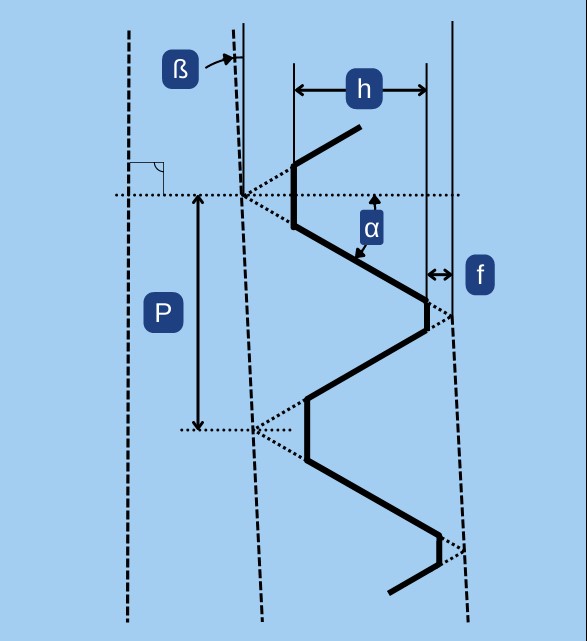
The tolerancing system for NPTF resembles the NPT standard’s requirements but is more strict in several respects:
- Taper angle tolerance.
- Truncation tolerances.
- Required gauging.
Taper Angle (ß) Tolerance
The taper angle (Beta) is defined in ASME B1-20.3 as 0.0625 +/-0.0050 Inch per an inch length. If we measure the pitch diameter at a particular location, move one inch along the axis and measure it again, we should measure a difference in diameter of 0.0625″.
I have no idea why an angle is defined in such a peculiar way; however, you can convert it to degrees using the below formula:
- The linear units are measured on the diameter, and the angle is measured “per side”. Therefore the 0.5 factor is applied.
- The tolerance field is about 60% compared to the field in regular NPT threads.
Truncation and Height Tolerances
- Dimensions are in Inches.
- The ASTM standard provides only the tolerance of the truncations.
- We calculated the height limits based on that.
- The tolerances depend only on the pitch.
- The tolerance field is about 60% compared to the field in regular NPT threads.
| TPI | Thread Height | Crest Truncation | Root Truncation | Head Angle | |||
| hmin | hmax | fmin | fmax | fmin | fmax | 2α (60°) | |
| 27 | 0.02338 | 0.02688 | 0.0017 | 0.0035 | 0.0035 | 0.0052 | +/- 2.5° |
| 18 | 0.03771 | 0.04121 | 0.0026 | 0.0043 | 0.0043 | 0.0061 | +/- 2° |
| 14 | 0.0514 | 0.0549 | 0.0026 | 0.0043 | 0.0043 | 0.0061 | +/- 2° |
| 11.5 | 0.06231 | 0.06661 | 0.0035 | 0.0052 | 0.0052 | 0.0078 | +/- 1.5° |
| 8 | 0.09185 | 0.09615 | 0.0052 | 0.0069 | 0.0069 | 0.0095 | +/- 1.5° |
Gauging for acceptance
- The NPT standard requires only an L1 Gage.
- NPTF requires, in addition to the L1 gage, also: L2, L3, and “Crest Check” gages.
NPSF – Nation Pipe Straight Fuel Thread
- NPSF threads are straight (cylindrical) instead of tapered.
- They are internal only, intended to mate with external tapered NPTF threads.
- They are more economical to manufacture than tapered threads.
- Sealing is not guaranteed since root and crest interference will not occur for all threads.
- NPSF threads are used with ductile materials that can adjust at assembly to the external taper during assembly.
- They should not be used in hard/brittle materials.
- Since they are cylindrical, the definition of pitch, major and minor diameters are more in-line with the methods used in regular metric or inch threads.
NPSF Thread Dimensions chart
| Thread | Pitch Diameter | Min. Minor Diameter | Min. Thread Length |
|---|---|---|---|
| 1/16" - 27 NPSF | 0.2768 - 0.2803 | 0.2482 | 0.31 |
| 1/8" - 27 NPSF | 0.3692 - 0.3727 | 0.3406 | 0.31 |
| 1/4" - 18 NPSF | 0.4852 - 0.4904 | 0.4422 | 0.47 |
| 3/8" - 18 NPSF | 0.6205 - 0.6257 | 0.5776 | 0.5 |
| 1/2" - 14 NPSF | 0.77 - 0.7767 | 0.7133 | 0.66 |
| 3/4" - 14 NPSF | 0.9805 - 0.9872 | 0.9238 | 0.66 |
| 1" - 11 1/2 NPSF | 1.2284 - 1.2365 | 1.16 | 0.78 |
- Dimensions in Inches
NPSI – Nation Pipe Straight Intermediate Thread
- NPSI threads are straight (cylindrical) instead of tapered.
- They are internal only, intended to mate with external tapered PTF-SAE short threads.
- They have slightly larger diameters than the NPSF threads.
- They are more economical to manufacture than tapered threads.
- Sealing is not guaranteed since root and crest interference will not occur for all threads.
- NPSI threads are used with hard/brittle materials that can adjust at assembly to the external taper during assembly.
- Since they are cylindrical, the definition of pitch, major and minor diameters are more in-line with the methods used in regular metric or inch threads.
NPSI Thread Dimensions chart
| Thread | Pitch Diameter | Min. Minor Diameter | Min. Thread Length |
|---|---|---|---|
| 1/16" - 27 NPSF | 0.2791 - 0.2826 | 0.2505 | 0.31 |
| 1/8" - 27 NPSF | 0.3715 - 0.375 | 0.3429 | 0.31 |
| 1/4" - 18 NPSF | 0.4886 - 0.4938 | 0.4457 | 0.47 |
| 3/8" - 18 NPSF | 0.624 - 0.6292 | 0.5811 | 0.5 |
| 1/2" - 14 NPSF | 0.7745 - 0.7812 | 0.718 | 0.66 |
| 3/4" - 14 NPSF | 0.985 - 0.9917 | 0.9283 | 0.66 |
| 1" - 11 1/2 NPSF | 1.2338 - 1.242 | 1.1655 | 0.78 |
- Dimensions in Inches
PTF-SAE Short Thread
External
- PTF-SAE Short External threads conform in all parameters with NPTF external threads, except that the thread length is shorter by one thread from the small (entering) end.
- They are designed for applications with limited clearance.
- They are slightly cheaper to produce than standard NPTF threads.
- PTF-SAE SHORT external threads are intended for assembly with NPSI or NPTF internal threads.
Internal
- PTF-SAE Short Internal threads conform in all parameters with NPTF internal threads, except that the thread length is shorter by one thread from the large (entering) end.
- They are designed for thin materials where thickness is insufficient for the full thread length of NPTF
- They are slightly cheaper to produce than standard NPTF threads.
- PTF-SAE SHORT internal threads are intended for assembly with NPTF external threads.
- They cannot be assembled with PTF-SAE short external threads.


